
- All
- Product Name
- Product Keyword
- Product Model
- Product Summary
- Product Description
- Multi Field Search
Views: 0 Author: Site Editor Publish Time: 2026-10-06 Origin: Site


A single millimeter of dimensional deviation can easily derail an entire manufacturing setup. You might be bolting together a multi-tier automated conveyor system, only to find the final mounting bracket refuses to sit flush against the upright support. Exacting precision is vital for any sturdy structural backbone. When dimensional management fails, it triggers cascading project delays. Structural integrity drops. Budgets inflate.
Navigating the complex world of metal fabrication requires a deep understanding of material behavior. How do you strike a balance between structural performance and manufacturing realities? This guide breaks down how to specify the right tolerances for your engineering application. We will also explore the critical threshold where raw thermo-mechanical forming hits its physical limits. At that point, secondary machining becomes an absolute necessity for advanced applications.
Match Tolerance to Application: Not all structures require aerospace-grade precision. Standard commercial allowances are frequently sufficient for basic static supports. Conversely, automation systems and robotics strictly demand high-precision components to function safely.
Understand the Standards: Familiarizing yourself with global manufacturing benchmarks empowers you to communicate exact technical requirements with your supplier. EN 12020-2 governs precision profiles, while EN 755-9 dictates standard commercial use.
Cost vs. Precision: Tighter dimensional constraints inherently increase manufacturing costs. They force lower press speeds and cause higher rejection rates. Optimizing your design to avoid over-specifying is crucial for budget management.
CNC is the Ultimate Backup: Raw forming methods sometimes cannot achieve the required tightness for critical mounting interfaces. When this happens, utilizing post-extrusion subtractive machining is the most reliable and accurate solution.
Avoid Common Mistakes: Drastic variations in wall thickness and overly complex internal cross-sections remain the leading causes of costly specification errors. These design flaws cause massive warping during the cooling phase.
Before finalizing the bill of materials for an engineering project, you must grasp the mechanical realities of metal fabrication. Tolerances dictate the allowable deviation from a theoretically perfect mathematical dimension. In the realm of metal shaping, these microscopic deviations are a natural, unavoidable byproduct of the manufacturing method itself.
The current industrial landscape is shifting rapidly. Recent market analysis regarding structural metal framing highlights a distinct polarization in modern manufacturing demands. As industries transition toward automated robotics, semiconductor fabrication, and high-density optical sorting, the demand for ultra-precise structural components has surged. Equipment builders can no longer rely on standard catalog variances.
Meanwhile, procurement teams handling traditional warehousing and static ergonomic setups are actively moving away from over-engineered parts. They prioritize cost-effective standard modularity. This evolving landscape underscores a key point. Selecting the right Extrusion Tolerance is no longer a generic purchasing task. It is a highly strategic engineering decision tailored to the specific functional tier of the end product.
At its core, this metric defines the acceptable limit of physical variation in the dimensions of a formed metal part. This encompasses slight variations in overall width, wall thickness, longitudinal straightness, surface flatness, and angular twist.
The creation of these metal shapes is an intense thermo-mechanical process. A solid metal billet is heated to a glowing 400 to 500 degrees Celsius, forcing it into a highly plastic state. A massive hydraulic ram then pushes this heated material through a precisely engineered steel die. As the metal exits the tooling, it is rapidly quenched using controlled air or water systems. The material undergoes extreme thermal expansion followed by rapid contraction. Consequently, slight dimensional shifts naturally occur. Coupled with the microscopic wear the steel die experiences from immense friction, standardized allowances exist to quantify these natural variations. This ensures the final component remains predictable for design engineers.
When constructing a heavy-duty structural unit, dimensional accuracy directly dictates both the fluidity of the assembly process and the long-term integrity of the equipment. Many modern setups utilize modular T-slot systems. They heavily rely on standardized brackets, specialized nuts, and fasteners to lock individual struts together.
If the dimensional accuracy is poorly managed, the external faces of the strut may be slightly oversized or undersized. Oversized channels cause T-nuts to bind and jam. This brings assembly lines to a frustrating halt. Undersized dimensions result in loose, sloppy connections. In dynamic applications involving motor mounts or vibrating conveyor belts, these micro-movements will degrade the joints over time. You will eventually face severe vibration harmonics, accelerated wear on moving parts, and catastrophic failure of the Industrial Frame.
To accommodate vastly different engineering needs and financial constraints, the metal fabrication industry categorizes dimensional accuracy into two primary tiers. Grasping the distinction between Standard Commercial and High-Precision prevents procurement teams from unknowingly paying premium prices for unnecessary perfection.
Commercial allowances represent the baseline dimensional accuracy offered by global manufacturers. They account for standard thermal shrinkage and typical die wear expected during normal, high-volume production runs. They do not require specialized, slower manufacturing techniques.
Depending on the overall footprint of the cross-section, standard allowances typically permit a deviation ranging from ±0.15mm to ±0.50mm on critical dimensions. This tier is exceptionally well-suited for static workbenches, basic machine safety perimeters, and material handling carts. In these applications, a fraction of a millimeter gap does not impede mechanical functionality.
High-precision requirements are significantly stricter. They frequently cut the allowable deviation of commercial standards in half. Achieving this elevated level of precision requires the manufacturer to drastically slow down the press speed. They must utilize specialized high-grade steel dies and implement rigorous, multi-stage cooling controls to prevent warping. Because rejection rates during quality control are inherently higher, this tier commands a premium price.
Engineers typically reserve these strict specifications for linear motion guides, automated actuator housings, and robotic arm bases. They are also mandatory for optical inspection frames where exact sensor alignment is non-negotiable.
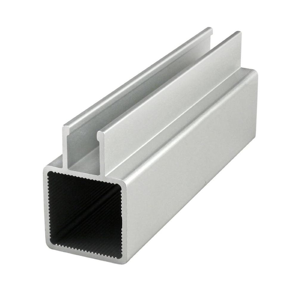
To establish a universal, unambiguous language between design engineers and factory floor operators, several international organizations have codified these allowable deviations. Referencing these specific benchmarks in your technical blueprints ensures your supplier understands exactly what level of quality is expected before the first billet is heated.
In the European and broader global markets, two frequently referenced frameworks dictate baseline quality.
EN 755-9 Standard Engineering Profiles: This specification covers the dimensions and form for standard components used in general engineering. It provides a relatively generous allowance for variations in wall thickness, overall width, and longitudinal straightness. If a technical drawing lacks a specific callout, most global manufacturers will automatically default to EN 755-9. It remains highly suitable for architectural applications and basic structural framing.
EN 12020-2 Precision Profiles: Regarded as the gold standard for high-precision components extruded from 6060 and 6063 alloys, EN 12020-2 imposes much stricter rules across all measurable metrics. The allowable twist or straightness deviation is significantly tighter. It strictly governs the parallelism of opposite walls. This makes it the mandatory standard for any structure designed to house linear bearings, pneumatic slides, or precision optical sensors.
For engineering teams operating within North America or managing diverse global supply chains, recognizing equivalent standards is vital. ASTM B221 is the primary North American standard outlining dimensional allowances for extruded bars, rods, and tubes. ISO 755 serves as the International Organization for Standardization equivalent. It closely mirrors the European framework to ensure cross-border manufacturing maintains consistent, predictable quality.
Selecting the appropriate dimensional constraint is a calculated exercise in risk management and financial planning. Engineering teams must critically evaluate the actual mechanical demands of the project. Stop relying on abstract concepts. Use this direct tier-based approach to match your design with real-world manufacturing parameters.
The fundamental purpose here is bearing static weight safely. For standard workbenches or perimeter fencing, specify a robust 6063-T5 alloy with standard EN 755-9 commercial tolerances. An acceptable deviation of ±0.30mm to ±0.50mm is perfectly fine. The fasteners and corner brackets will easily absorb this variance. Over-specifying here wastes your budget.
Factory structures are frequently disassembled, expanded, or reconfigured. If your design requires frequent modular adjustments or integration with specialized conveyor rollers, standard allowances might cause issues. Parts from different production batches may fail to align perfectly, creating a noticeable step at the joint. For these applications, specify EN 12020-2. Tightening the straightness constraint ensures automated components slide across joints smoothly without snagging.
Exceptionally heavy dynamic loads and precision sensors dictate the tightest dimensional control. When a strut houses a high-speed linear rail, the mating surfaces must sit perfectly flush. If they do not, vibration harmonics will destroy the bearings. Raw extrusion cannot meet these demands. You must specify a hybrid approach. Design the raw profile with an extra 0.5mm of sacrificial wall thickness. Then, mandate post-extrusion CNC machining to hit a surface flatness of ±0.01mm. This guarantees your M8 fasteners won't fail under shear stress.
Even the most advanced digitally controlled presses cannot overcome fundamentally flawed geometries. Many dimensional failures are not the fault of the factory. They are the result of design choices that directly conflict with the physical realities of thermo-mechanical forming.
Applying aerospace-level precision to a standard workbench leg is a remarkably common and costly mistake. Over-specifying does not make the structure perform better. It merely inflates tooling costs, extends lead times, and generates unnecessary friction between procurement teams and suppliers. Always apply constraints based strictly on functional necessity.
Drafting a cross-section with sudden changes in wall thickness is the leading cause of dimensional failure. When a design features thick structural nodes directly adjacent to paper-thin cooling fins, the metal cools at vastly different rates upon exiting the die. Thin sections harden and shrink rapidly. Thick sections retain heat. This severe thermal imbalance creates massive internal stresses. The metal will bow, twist, or warp uncontrollably. Robust designs maintain uniform wall thickness wherever physically possible.
Designers frequently fixate entirely on cross-sectional dimensions like width and height. They completely forget about longitudinal metrics like twist and straightness. A strut may measure exactly 40mm by 40mm at its end. However, if it suffers from a 2-degree twist over a two-meter length, assembling a square frame becomes physically impossible. Always explicitly specify straightness and twist limits, particularly for lengths exceeding one meter.
Solid shapes are relatively straightforward to push through a die. Hollow shapes require a highly complex porthole die. The solid heated billet is forcefully split into multiple streams inside the tool. It is then welded back together under immense pressure before exiting. Because of these chaotic internal flow dynamics, hollow shapes with multiple intricate internal cavities are inherently more difficult to keep within tight boundaries. Simplifying internal geometries significantly improves batch-to-batch consistency.
Factory tolerances apply strictly to the raw, mill-finish metal. Most structural components require surface treatments to prevent oxidation and improve aesthetics. Standard anodizing typically adds a negligible microscopic layer of 10 to 25 microns. Powder coating, on the other hand, can easily add 50 to 100 microns of thickness to the surface. If a designer calls for a tight fit for a T-slot channel but forgets to account for the thickness of the paint, the hardware will simply refuse to slide into the channel after coating.
There are specific scenarios in advanced manufacturing where even the strictest EN 12020-2 precision standards fall short. Semiconductor handling and automated optical inspection are prime examples. When engineering highly sensitive equipment, relying solely on raw forming processes introduces unacceptable risk.
You must accept that pushing heated metal through a steel die is a bulk-forming process. The material is subjected to stretching during the cooling phase to ensure general straightness. Because of the chaotic physics involved, there is a hard physical limit to how mathematically perfect the raw output can be. If an assembly requires a surface flatness of ±0.01mm for mounting a high-speed linear rail, raw forming simply cannot achieve this. The factory's expertise does not change the laws of physics.
When raw forming reaches its physical limitations, secondary subtractive machining steps in as the ultimate corrective solution. By securing the raw part in a precision fixture and utilizing multi-axis milling equipment, it is transformed into a highly accurate CNC Profile.
Secondary machining completely removes the unpredictable variables of thermal expansion and die wear. It guarantees exact hole placements, perfectly flat datum surfaces, and precise cut-to-length dimensions without stack-up errors. For high-end applications, engineers frequently design the initial shape with slightly thicker walls, intentionally leaving extra sacrificial material. The milling center then carves away this extra material to achieve a perfectly flat, ultra-tight surface for mounting critical automation components. This hybrid approach is the most cost-effective pathway to achieving flawless precision.
Feature / Metric | Typical Raw Extrusion Limit | CNC Machining Capability | Impact on Assembly |
|---|---|---|---|
Linear Tolerance | ±0.15mm to ±0.50mm | ±0.01mm to ±0.05mm | Determines how seamlessly modular joints and brackets align without forced fitting. |
Surface Flatness | 0.20mm per 100mm | 0.02mm per 100mm | Critical for mounting linear guide rails. Poor flatness causes vibration and wear. |
Hole Positioning | ±0.50mm via extrusion | ±0.01mm | Ensures exact alignment for bolts, dowel pins, and third-party automated components. |
Angularity 90 Degrees | ±1.0 degree | ±0.05 degree | Prevents the structure from skewing out of square during final assembly. |
Specifying the correct dimensional constraints on your CAD drawings is merely the first step. The ultimate success of your structural backbone depends entirely on the capabilities, quality control protocols, and technical expertise of the manufacturing partner you select. Vetting suppliers requires a meticulous approach. Focus on their adherence to global standards and their ability to handle complex secondary operations in-house.
When sourcing materials for critical infrastructure, collaborating directly with an Original Equipment Manufacturer specializing in custom fabrication is highly recommended. Unlike standard catalog distributors, specialized OEM facilities possess deep engineering infrastructure. They control every variable of the production lifecycle, from initial billet casting and die design to final surface treatment.
A premier supplier operates under strict quality management systems, most notably ISO 9001. Inquire about their in-house metrology laboratories. Reliable manufacturers utilize advanced measurement tools, such as Coordinate Measuring Machines and laser scanners. They verify that every batch perfectly matches the specified criteria before it leaves the factory floor. Transferring raw shapes from a primary mill to a separate third-party machine shop introduces severe logistical risks. It often leads to disputes over accountability if dimensional errors occur. Partnering with a facility that manages both the primary forming and the secondary CNC milling under one roof ensures seamless communication. It guarantees a flawless final Aluminum Profile.
Selecting the correct dimensional specification is the absolute linchpin of building a successful, durable structure. Clearly understand the operational differences between standard commercial allowances and high-precision requirements. Reference the correct international standards like EN 12020-2. Know exactly when to invest in secondary subtractive machining. By doing this, engineering teams can entirely avoid costly design errors. Always evaluate the specific mechanical and dynamic demands of your project before finalizing your blueprints.
Are you ready to optimize your structural designs and eliminate assembly bottlenecks? Choosing the right specification does not have to be a guessing game. Explore our comprehensive range of custom manufacturing solutions and find the exact specifications for your project at EWHA LU. Our engineering team is ready to help you strike the perfect balance between precision and cost-efficiency, ensuring your structural components perform flawlessly for years to come.
Standard allowances generally follow the EN 755-9 European or ASTM B221 North American specifications. Depending on the overall size, wall thickness, and specific dimension of the cross-section, standard commercial tolerances usually allow for a deviation ranging from ±0.15mm to ±0.50mm on critical measurements. These standards also dictate acceptable limits for longitudinal straightness, twist, and angularity. For the vast majority of static structures, workbenches, and basic safety enclosures, these standard allowances are more than sufficient to ensure proper fit and structural integrity without unnecessarily driving up manufacturing costs.
The relationship between dimensional accuracy and manufacturing cost is exponential rather than linear. Requesting tighter constraints requires the factory to utilize significantly slower press speeds to minimize thermal distortion. It also necessitates far more frequent die maintenance, as even microscopic wear on the steel tooling will push the metal out of spec. Additionally, stricter requirements inherently lead to higher rejection rates during quality control inspections. All of these operational factors significantly increase the final cost per kilogram. Specifying only the level of precision you genuinely need keeps your project economically viable.
Yes. Secondary subtractive machining is the standard, highly effective engineering solution for correcting raw forming deviations. If an assembly requires ultra-precise mounting surfaces, exact hole alignments, or perfectly flat mating faces that raw forming cannot physically achieve, the raw material undergoes post-processing. By securing the piece in a multi-axis milling machine, precision cutting tools remove sacrificial material to create a highly accurate finished component. This process corrects surface flatness, ensures perfect dimensional accuracy, and establishes highly reliable datum points for complex automated assemblies.
EN 755-9 is the recognized European standard for general commercial dimensional allowances. It is designed primarily for standard architectural and basic structural applications. It provides a wider allowance for physical variation, making the parts highly cost-effective to produce in massive volumes. In stark contrast, EN 12020-2 is the specific standard for precision components. It demands much tighter allowances for cross-sectional dimensions, straightness, flatness, and twist. Engineers explicitly specify EN 12020-2 when designing advanced frameworks for linear motion systems, robotics, and automation, where minimal deviation is critical for dynamic mechanical performance.
The manufacturing physics for hollow shapes are fundamentally more complex than for solid bars. To create a hollow internal cavity, the heated metal must be forcefully pushed through a specialized tool known as a porthole die. Inside this die, the solid material stream is split apart to flow around a central steel mandrel. It is then fused back together under immense heat and pressure before exiting. Because of this chaotic internal material flow, the presence of longitudinal weld seams, and the uneven cooling rates between the internal and external walls, hollow shapes are significantly more susceptible to thermal distortion. Consequently, global engineering standards grant hollow shapes slightly wider dimensional allowances compared to simple solid geometries.
The chemical composition of the alloy directly impacts its extrudability and thermal behavior. Harder alloys, such as 7075 or 2024, require immense pressure to push through the die and are highly prone to internal stress and warping during the quench phase. Maintaining tight tolerances on these hard alloys is extremely difficult. In contrast, softer and more highly extrudable alloys like 6063 flow smoothly through complex dies and cool more evenly. This predictable flow characteristic makes 6063 the preferred choice when tight dimensional stability and intricate geometries are required.
Specifying high-precision requirements often adds several weeks to the standard manufacturing lead time. Standard commercial grades are produced at high press speeds with standard cooling protocols, allowing for rapid high-volume output. High-precision profiles require slower extrusion speeds, meticulous die corrections between trial runs, and significantly enhanced quality control inspections involving CMM verification. If secondary CNC machining is required to hit the final tolerances, the lead time will extend further to account for the additional subtractive manufacturing phase.


